The electron has an intrinsic spin angular momentum. A beam of electrons is said to be “polarized” if their spins point, on average, in a specific direction. In 1929, the British physicist Sir Nevil Mott raised the question of whether or not the effects due to electron spin and polarization could be observed directly. He proposed that spin could be detected in a double scattering experiment in which a beam of high energy, unpolarized electrons are scattered from a high-Z nucleus. In 1942, Schull, et al. demonstrated a polarized scattering asymmetry that was in agreement with Mott’s calculated value. Today, the area of polarimetry has shifted towards measurement of electron polarization in other areas of physics.
Principles of Mott Scattering
Consider a single electron scattering from a bare, high-Z nucleus. As the electron passes through the electric field of the nucleus, a magnetic field is produced in the reference frame of the electron.
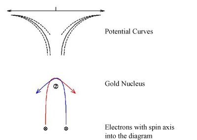
There are two forces that act on the electron as it approaches the Au nucleus, one due to the magnetic field and one due to the electric field. Because the electron has a spin angular momentum, the force exerted by the magnetic field depends on whether the electron scatters to the left or right. If the potential scattering curves are plotted for the electron, the curves become skewed one way or the other depending on the electron’s spin. This leads to an asymmetry in the left/right scattering probabilities:
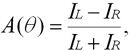
where IL and IR are the currents detected in the left and right channels of the polarimeter. Another important parameter in discussing Mott polarimeters is the figure of merit:

where I0 is the current entering the polarimeter, I is the total scattered current, and Seff2 is the analyzing power of the apparatus:
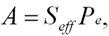
where Pe is the degree of electron polarization.
Why Build a New Mott Polarimeter?
Typical Mott polarimeters require electron energies of ~100 keV. To achieve these energies, high voltages are needed. Because of these voltage requirements, spacing between electrodes need to be sufficient to prevent electric discharge. The designed polarimeter uses energies of ~25 keV, requiring a smaller potential between the two hemispheres and hence a smaller overall design. More importantly, this device has a higher efficiency, defined to be I/Io. This is because of its smaller size. Increased efficiency improves the figure of merit.
Apparatus
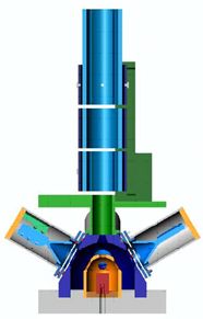
The designed polarimeter has three major sections: the electron transport system, the target chamber, and the detectors. The first section the electrons enter is the transport system. An Einsel lens configuration was used here. Two sets of four deflectors were used as the first and last lens element in this system. Below on the right is a cross sectional view of the entire polarimeter. The transport system is represented by the light blue cylinders.
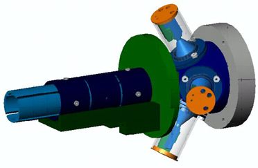
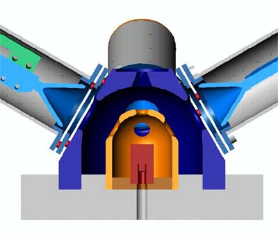
The electrons next enter the target chamber. The chamber consists of a cylindrical target within a polished stainless steel hemisphere. A common material used for the high-Z nuclei target is gold. Careful consideration must also be employed in choosing the material. Low-Z nuclei help minimize unwanted scattering, so aluminum was chosen. Scattered electrons then exit the target chamber and are collected in the detectors. The target chamber is shown in detail below. The transport system has been removed. The target is shown in red and the inner hemisphere in orange.
Results
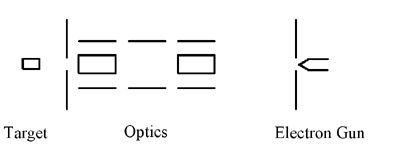
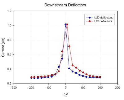
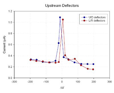
So far, the polarimeter has been assembled and the electron transport system has been tested and characterized. A simple filament and aperture were used to produce a small beam of electrons. The deflectors in the transport system were used to raster the beam across the opening to the target chamber. Current was then measured on the target. This is shown schematically below. The background current is due to electrons scattered upstream of the target.
Future Experiments
Further experiments need to be performed in order to fully characterize the polarimeter. These characteristics include: asymmetry measurements with polarized and unpolarized electron beams and efficiency measurements. Currently, the detectors and housings are being prepared to add to the system to make efficiency and asymmetry measurements for unpolarized beams.
References
- N. F. Mott, Proc. R. Soc. A 124 425 (1929).
- N. F. Mott, Proc. R. Soc. A 135 429 (1932).
- C. G. Shull, C. T. Chase, and F. E. Myers, Phys. Rev. 63 29 (1943).
- T. G. Anderson, et al, Rev. Sci. Instr., 72 7 (2001).
This project was funded by NSF Grant No. PHY-0099363 and UCARE